We have a client that needs a robot to do automated testing of dirt samples collected at volcanic sites. The dirt samples are placed in tiny crucibles, which are then placed on a rotating carousel that holds a number of samples. The robot must grab a sample, scan it, weigh it, and then place it back on the carousel and repeat the process for the remaining samples. Sounds simple enough.
We basically blew the whole budget on the robot arm knowing that we still had probably thousands to spend on a gripper solution. The cheapest grippers are pneumatic which require an air supply and all the related accessories, so the cost savings in the end aren’t that great and you’ll spend a lot for a gripper. The client had an old robot doing the job, but using that gripper seemed impossible due to it being ancient 90s technology, and no modern controller for it exists.
I figured before we spend all that time and money on an air solution, I decided to see if I couldn’t design a simple tool that would work without any moving parts. The concept is quite simple: design a tool with a pair of forks, spaced just right, that can slide under and up to grab the crucible. I’m sure this isn’t a novel solution but I haven’t seen anything off-the-shelf that would fit our exact need.
After a little thinking I went into Fusion 360 and imported a model of the robot. After taking some measurements I sketched out a quick design. I had a look in mind that I was going for and I think I captured it quite well. Of course it had to match the robot aesthetically.
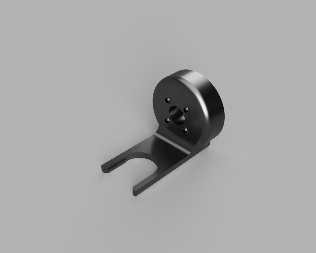
The spacing of the forks and the radius of the curve match the crucible at the “grab point” which ideally should be just a couple millimeters from the top of the crucible. Some protruding bits on the insides of the forks help keep the crucible from tipping forward and out. A few millimeters of vertical movement are required to secure and release the crucible, and it should clear the carousel shelves.
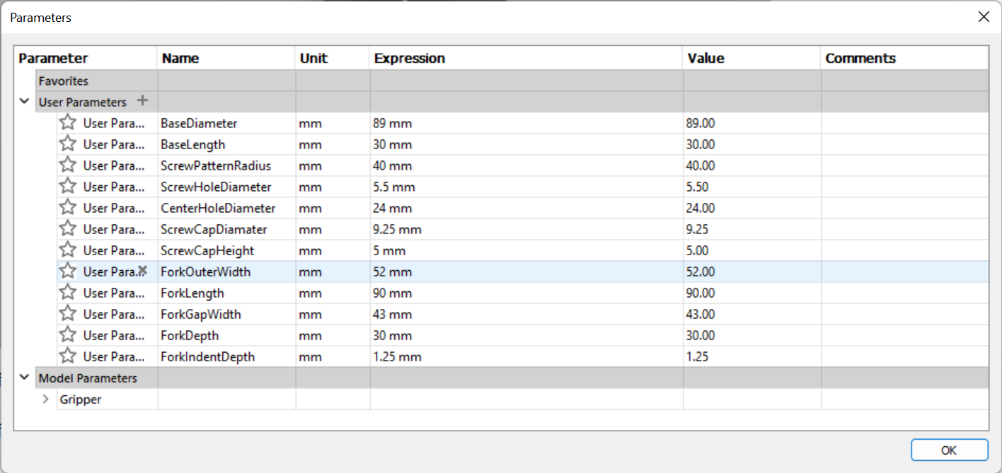
As a bonus, the entire design is parameterized. We can tweak almost any aspect of the design just by altering the parameters in Fusion 360.
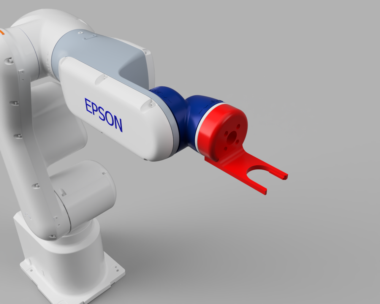
After modeling, I brought it into the model of our robot and made sure it fit and the screw holes lined up. I think the red color compliments the arm nicely.
Then I printed it out on the Voron in some red PolyLite ABS. The printer did an amazing job as usual. Shrinkage is quite minimal with this filament. The only thing I got wrong was that I made the screw holes a bit too narrow, and the forks were just a bit too close together. In order to fit the tool into the rack, it has to grip the crucible as high up as possible.
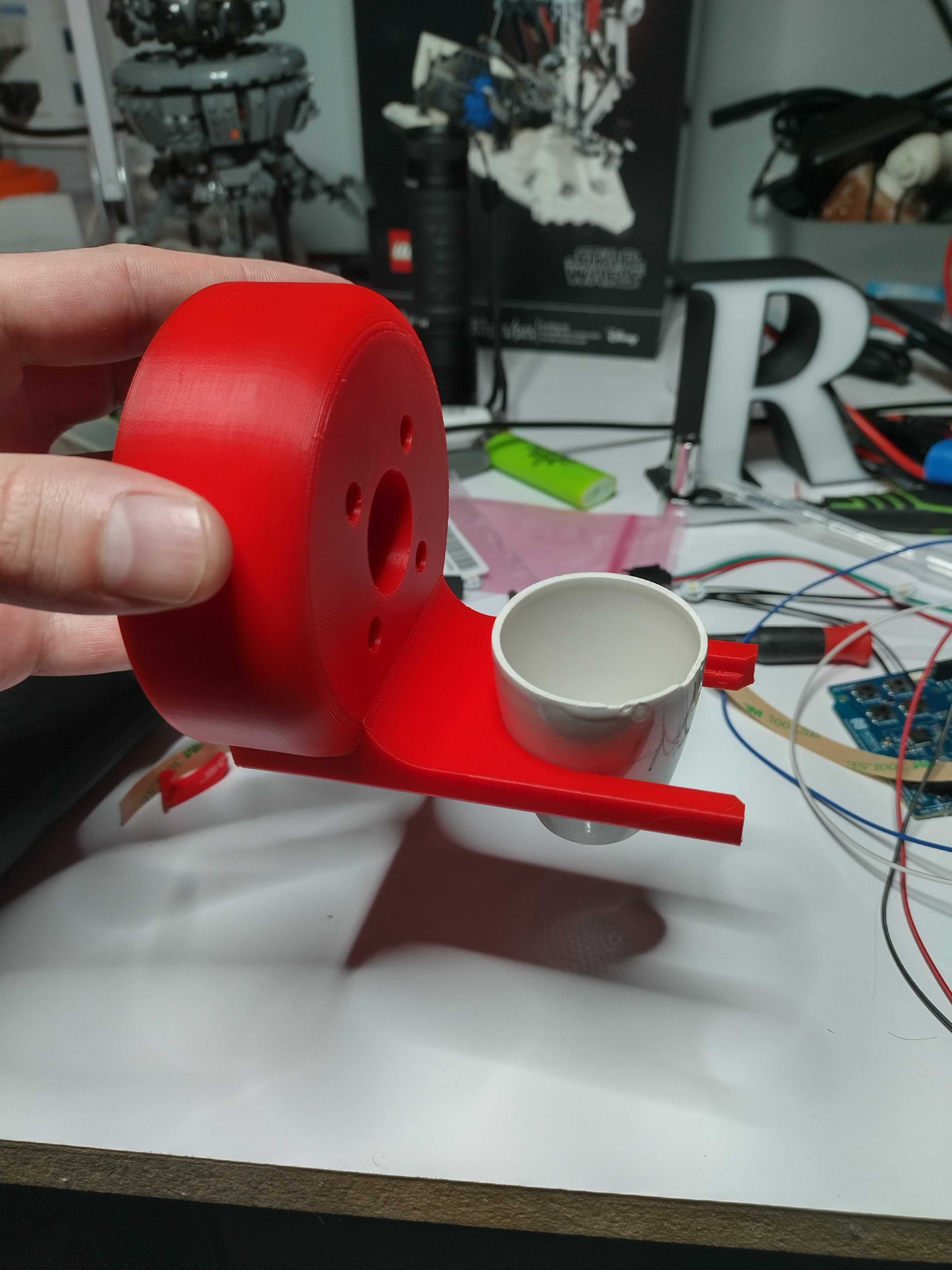
After making some adjustments I test printed another one. This time the screw holes were good and the grip was improved, but a third version is already in the works to widen the forks just a little bit. There was also some clearance issues, so I had to make the tool a bit longer to be able to fit between the shelves of the carousel without interference.
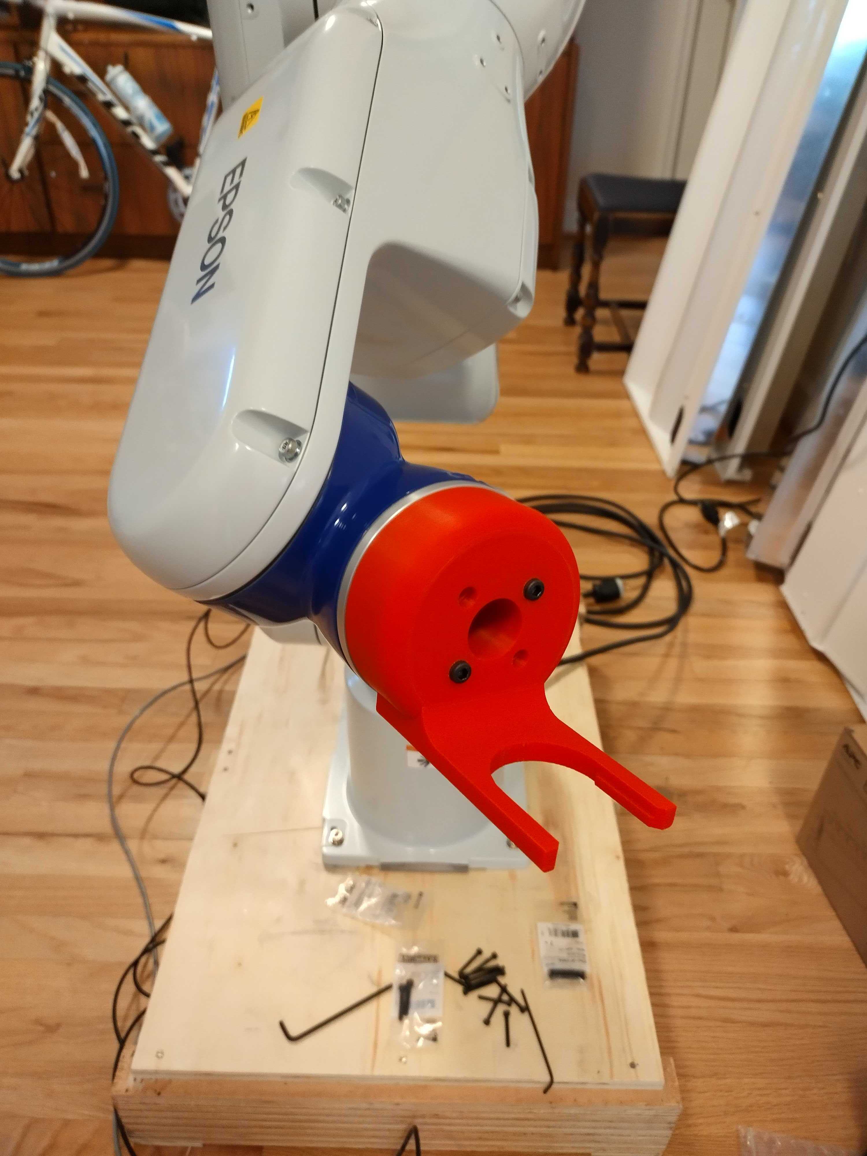
It was at this point that I realized that the tool mount used M5 screws instead of M4, so after a little tweaking in Fusion 360 I have another model printing and I’ll be experimenting with it tomorrow (as of this writing). I had to turn those screws pretty hard to get them to thread all the way through the plastic, but it worked well enough to test the fit and verify the screw pattern. Now all that’s left to do is test.
I can’t do much until we have the proper hardware to mount the robot to a test workspace that is solid enough to make accurate movements. So, to be continued…

Leave a Reply