Motivation
I got interested in the idea a few times over the last few years, but after seeing some cool power bank projects and tearing apart a few e-bike battery packs, I decided it was time to design my own battery bank. As I knew little about batteries before starting the project, I decided to start simple, and for the first prototype I created a simple 6-cell Lithium-Ion battery pack.
Design
I designed this pack around the common 18650 Li-Ion battery, which is very ubiquitous and cheaply available. I didn’t have a specific use case for a pack in any current project, so the design specifications are rather arbitrary. However, that did give me the opportunity to start with a simple proof of concept that I can use as a basis for more complex designs.
The most important feature I wanted was an integrated battery management controller that would provide overload and short-circuit protection, as well as cell balancing. The motivation for this is to be able to use any standard CC/CV charger to charge the pack. Eventually I’d like to include an integrated regulator for charging, so that the pack can be charged from any voltage source.
The battery management front-end I chose was the ISL94208 (datasheet). This front-end contains most everything needed to implement cell balancing and pack protection, requiring only a few external active components and a several passives. Most of my design is lifted right from the ISL94208EVZ evaluation kit.
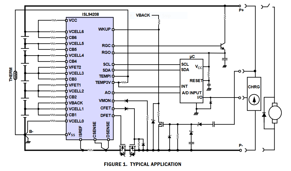
The chip is connected via I2C to an Atmel ATmega328P (essentially an Arduino Pro), which is required to implement cell balancing and other features. Some other models, themselves complete battery management controllers, are able to function independent of a microcontroller. However, I was interested in experimenting with my own cell balancing algorithms and possibly adding other features that would necessitate one.
The following table lists the overall design specifications:
| Specification | Value | Units |
|---|---|---|
| Number of Cells | 6 | |
| Output (Discharge) Voltage | ||
| Maximum (fully charged) | 25.2 | Volts |
| Nominal | 21.6 | Volts |
| Minimum (fully discharged) | 15 | Volts |
| Current | ||
| Discharge | 10 | Amps |
| Charge | 1 | Amps |
Charge and Discharge Paths
Taking a look at the example application circuits in the datasheet, there are two basic ways to lay out the charge and discharge paths: either as one integrated path, or as two separate paths. I decided to go with the separate charge and discharge paths, which will enable me to add a charge circuit to the pack later on, which will be just like a permanently-connected charger. If I were building a pack designed to be charged and discharged via the same connector, I’d probably go with the integrated path.
Assembly
The board was ordered from JLCPCB with standard options (2-layer, 1oz copper, etc). This is the third or fourth board I’ve had made and I haven’t had any complaints so far (that weren’t my fault).
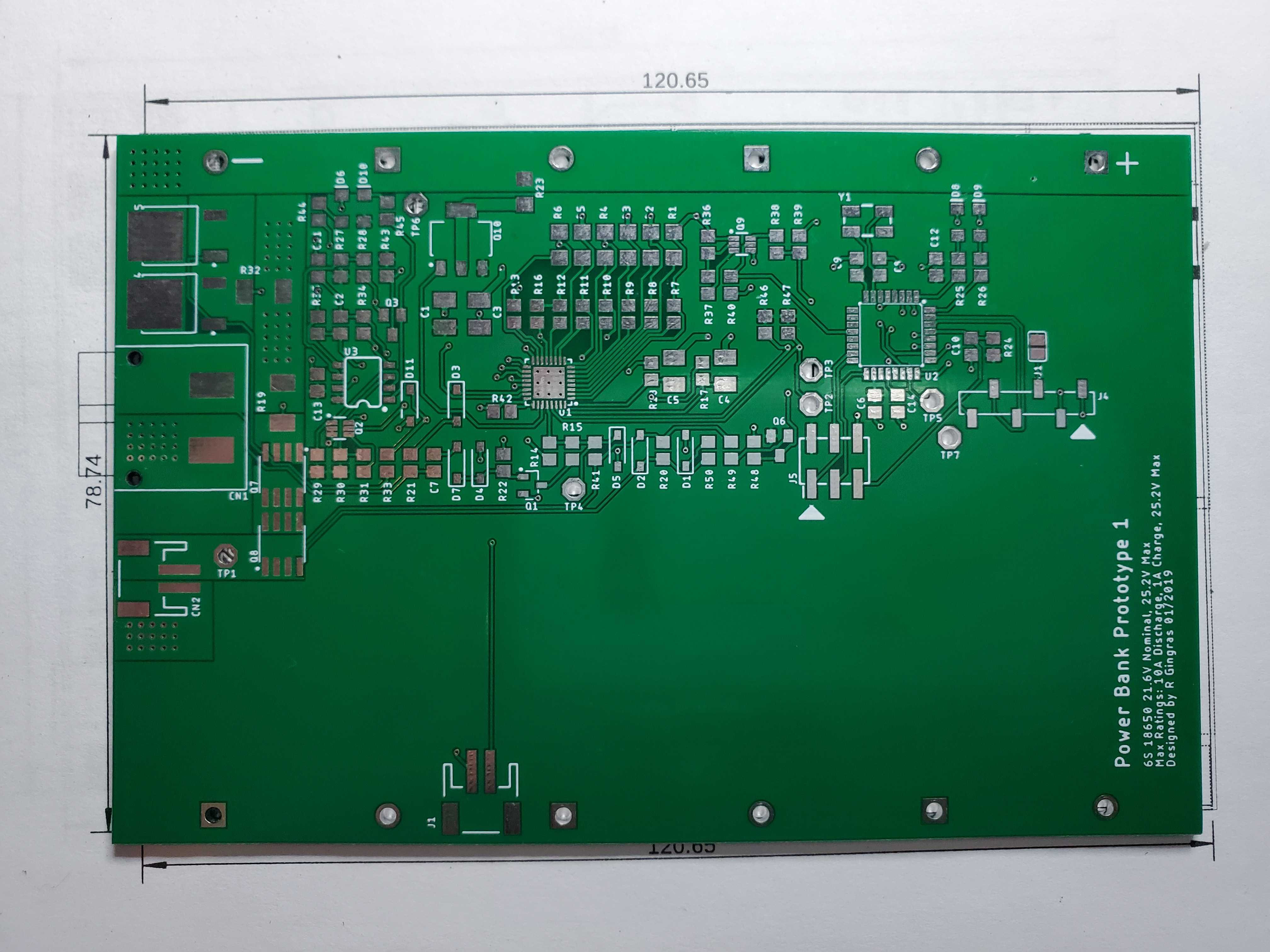
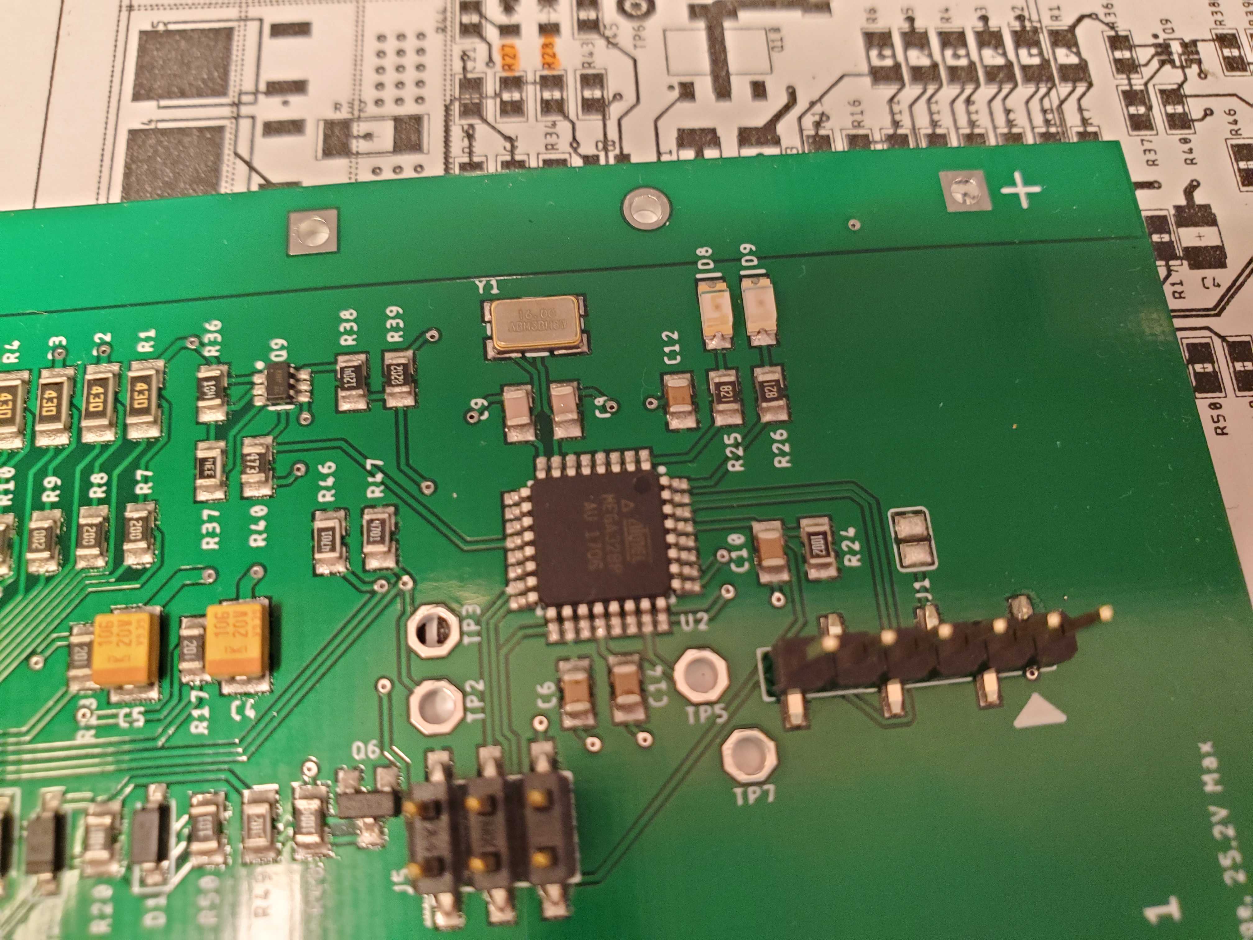
Next step was to stencil and place components:
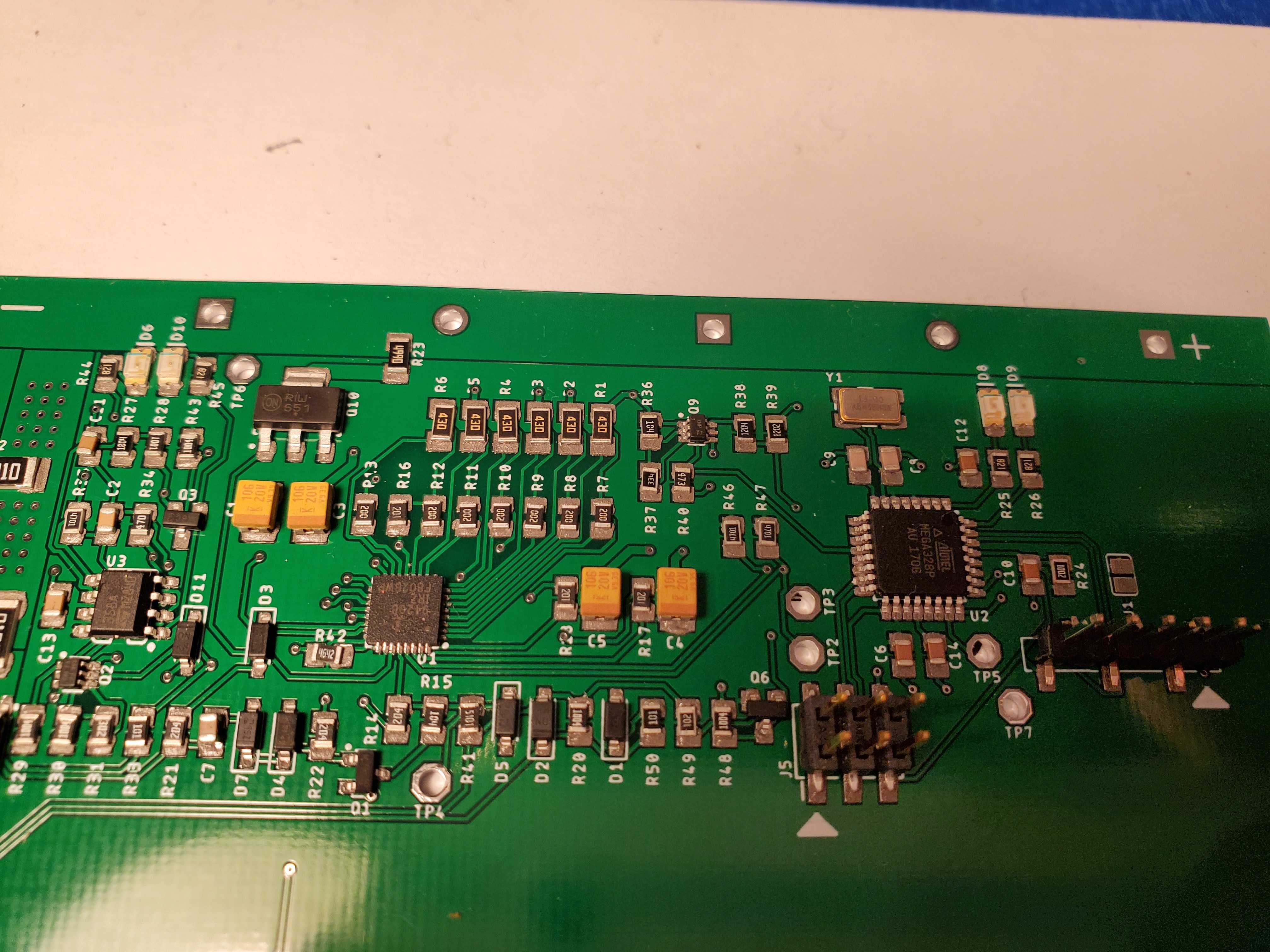
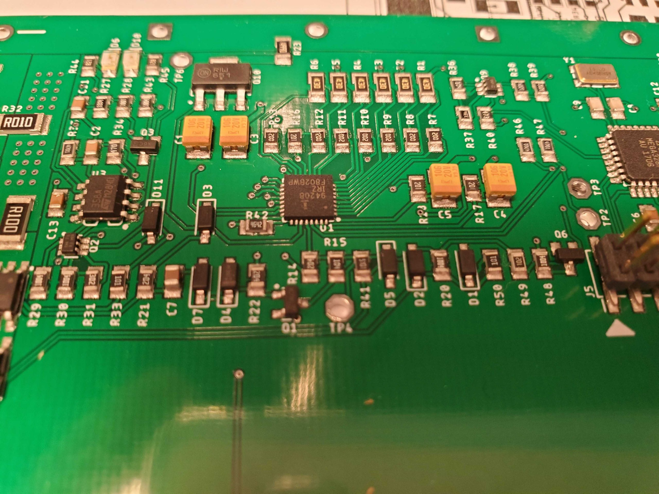
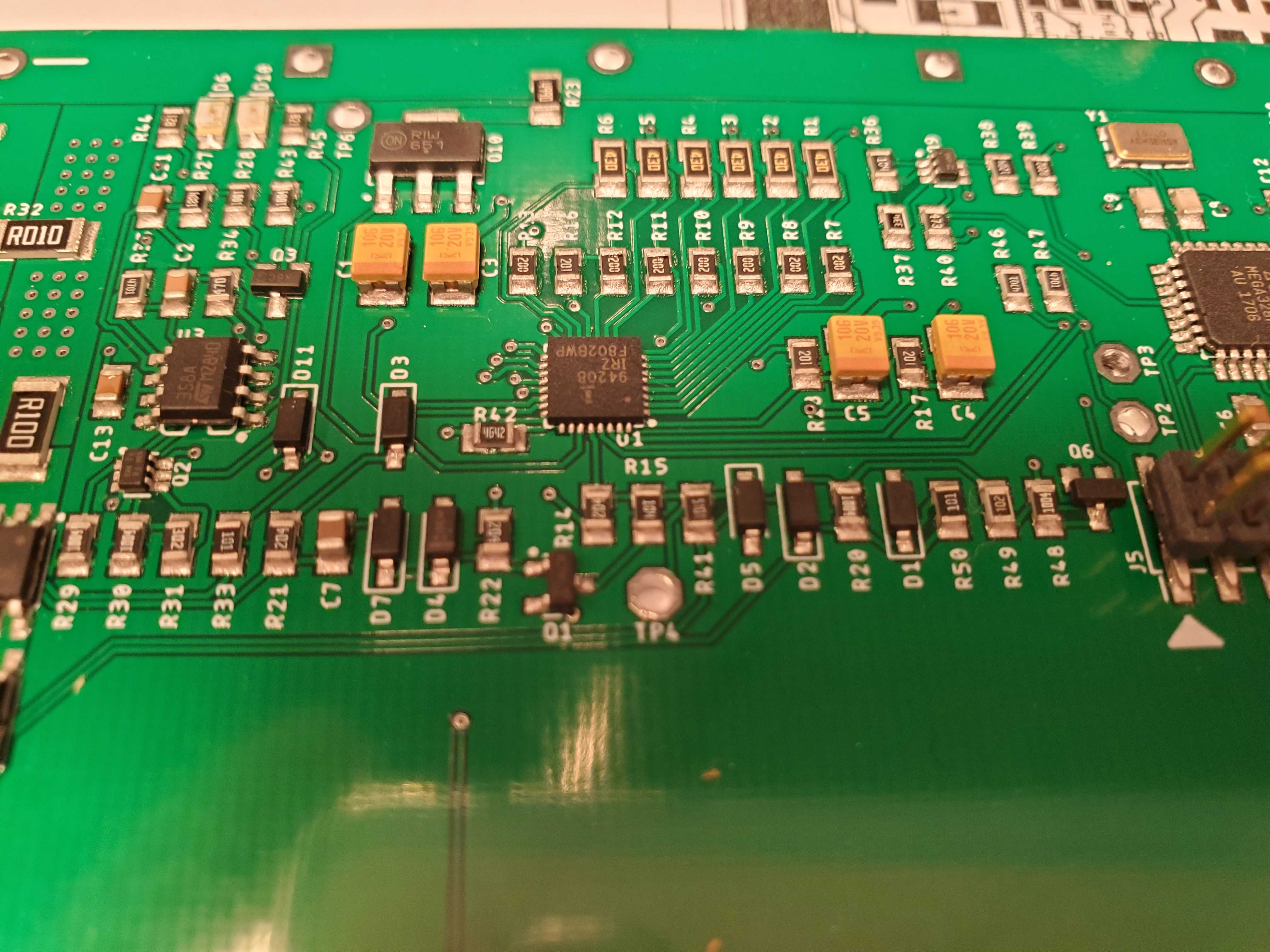
In all my previous projects using reflow, I used lead-free solder paste, which turned out to be a mistake. Since the oven isn’t super exact, it is very easy to burn things like connectors when reaching higher temperatures (over 200C). This time around I used low-temperature leaded solder paste and the results were much better:
Testing
The first test was a partial failure. I’m not sure if it was not enough time in the oven or if there was an issue with a component, but it seemed there was a short between the bottom cell positive terminal and ground through one of the balance resistors, resulting in that cell bleeding current constantly.
Another issue was that I forgot to place a capacitor on the reset line to prevent the FTDI cable from holding the reset line low, preventing the microcontroller from being programmed easily. That made uploading new code a bit of a pain.
Despite those issues, I was able to power on the pack and upload a simple sketch that tested ISL94208 communication and the LEDs. After verifying both worked, I made a few tweaks to the schematic and ordered a new version of the board.
First Revision
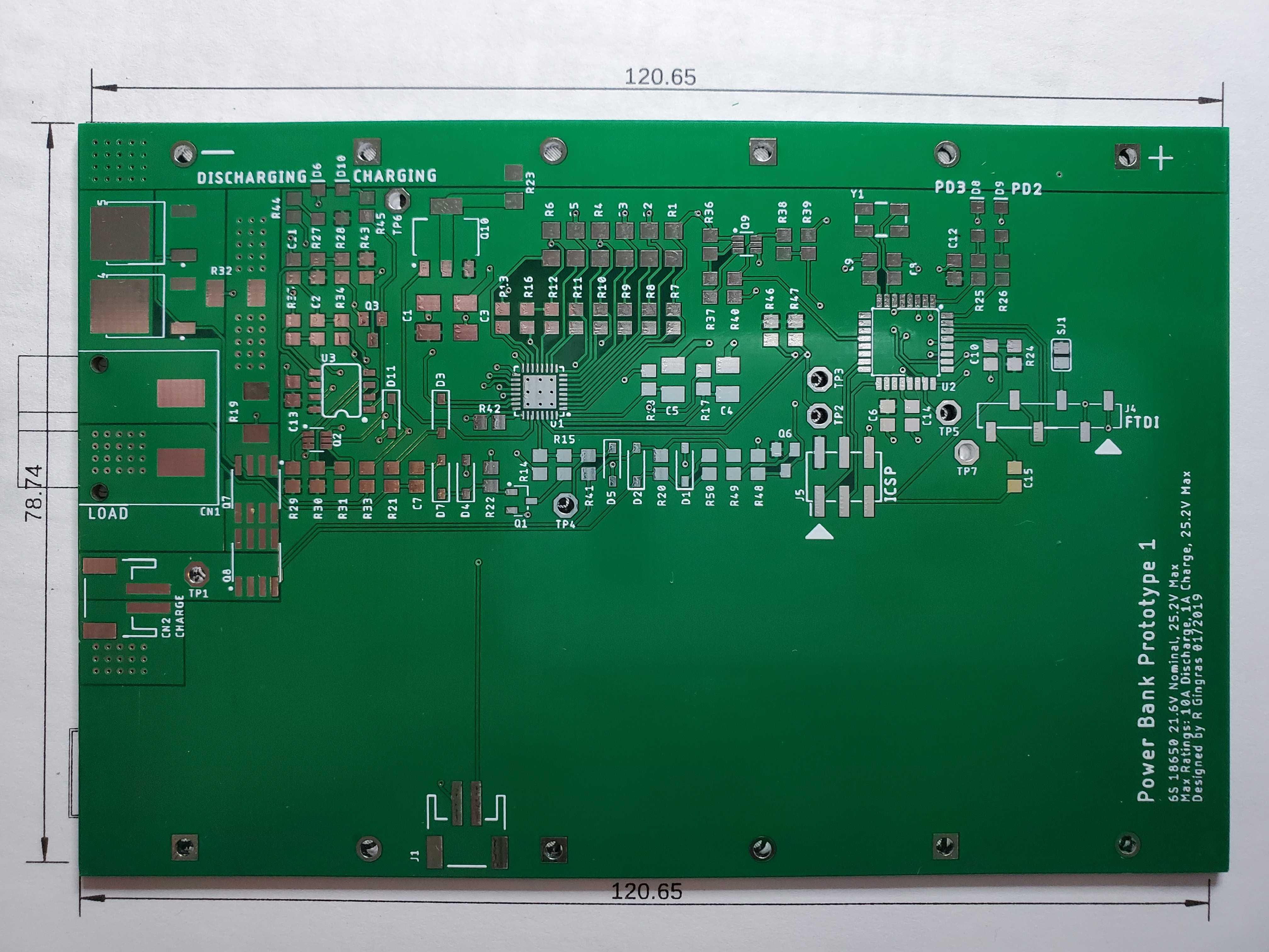
For the first revision, I increased soak and peak time to make sure that all of the solder was fully molten before cooling. After inserting all the cells into the pack I did not see any shorts or current being drawn, so I can only assume that what happened initially was probably a short, so lesson learned.
After connecting the pack to the computer with the FTDI cable and loading the Arduino bootloader, I now was able to upload sketches like it was any normal Arduino. All features of the ISL94208 were available and the chip seemed to work just fine.
There was one final issue, it seems I forgot a base resistor on Q3 which is part of the charge indicator circuit. The indicator itself works fine, but the LED is always on while the pack is active. A bit annoying, but I can wait to fix it until the next iteration.
Firmware
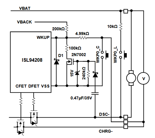
The ISL94208 and microcontroller remain powered off while the pack is not in use, and are only powered on while the pack is charging or discharging. While powered off, a wake-up circuit monitors the WKUP pin for a low or high pulse, depending on the WKUP polarity setting.
When a load or charger is connected, the WKUP pin of the ISL94208 is pulled low and it wakes up, in turn powering up the microcontroller. The firmware first sets some configuration in the ISL94208 and then runs a check to see if there is a charger connected by reading the state of the WKUP pin.
If the WKUP pin is still low, we can assume a charger is connected (a powered-on charger should pull the negative side of the charger connection near ground). The firmware then enables CFET and DFET and waits a few seconds until it detects charge current. If no charge current is detected within the specified period (CONF_SLEEP_TIMEOUT), then the pack goes back to sleep. Otherwise, the cell balancing algorithm begins until the charger is disconnected, or the pack reaches the charge threshold voltage (CONF_CHARGE_CUTOFF_THRESH).
If the WKUP pin is high, we can assume a load was connected (a connected load will pull the negative side of the load connection to pack voltage, causing the WKUP pin to be pulled low momentarily). The discharge FET is enabled and the controller re-enters sleep mode if no discharge current is detected within the configured period. Once discharge current drops below the minimum threshold (about 100mA) the controller again enters sleep mode. If the pack voltage drops below the minimum discharge threshold (CONF_DISCHARGE_CUTOFF_THRESH) then discharging is halted and the pack enters sleep mode.
Balancing Algorithm
Since a typical battery pack contains multiple individual cells connected together in series, sometimes with each of those cells in parallel with other cells, a problem can arise as any capacity mismatch between the cells can result in decreased capacity for the whole pack. Cell balancing is employed to even out the voltages among the cells in the pack, thereby increasing the life and capacity of the pack.
Practically speaking, the simplest form of cell balancing is called passive cell balancing and is accomplished by placing a FET and load resistor in parallel with each cell of the pack:
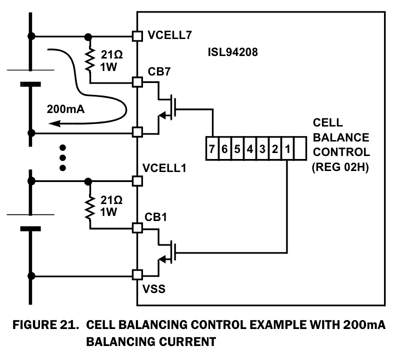
To divert charge current from a cell, the controller activates the balance FET for that cell and a fraction of the charge current is dissipated in the load resistor. How much current is dissipated is determined by the value of the balance resistor. At max cell voltage, which is about 4.2V and assuming a 21-ohm resistor, we’d dissipate about 200mA while the switch is active. As you can imagine, the major drawback of passive balancing is that some of the charge current is wasted in the form of heat dissipated in the balance resistor.
You can learn more about cell balancing by reading the Wikipedia article.
The passive balancing algorithm simply polls the cell voltages on a fixed interval, enabling the balancing FET for the cell with the highest voltage, and leaving it on until another cell becomes the highest voltage cell, and so on. Balancing during charge and discharge cycles can be enabled separately (CONF_BAL_CHARGE and CONF_BAL_DISCHARGE).
Overload and Short-Circuit Protection
The ISL94208 contains several protection functions:
- Charge over-current
- Discharge over-current
- Short-circuit
- Over-temperature
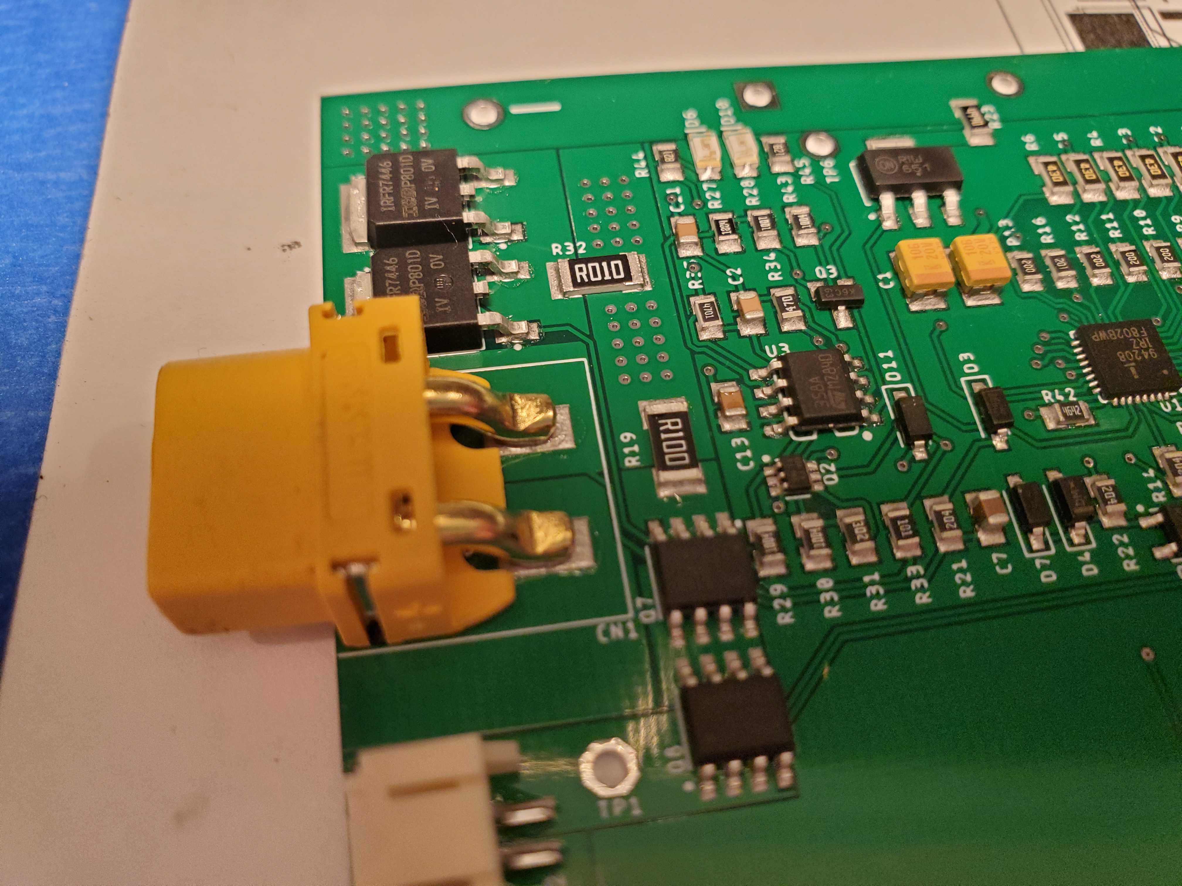
When the controller detects an overload condition, it is able to isolate the battery pack from the load or charger by switching off the charge/discharge FETs. The charge and discharge sense resistors (R19 and R32) set the currents that will trigger overload conditions.
In the event of a short-circuit condition, the ISL94208 provides the VMON pin to enable the microcontroller to detect if a load is still present, which could mean a short-circuit condition still exists. If so, the battery pack eventually re-enters sleep mode.
The delay between the detection of an overload or short-circuit and the deactivation of the FETs can be programmed via register in the ISL94208, as well as the voltage thresholds. In the firmware these are defined by CONF_OC_CHARGE_THRESH and CONF_OC_DISCHARGE_THRESH.
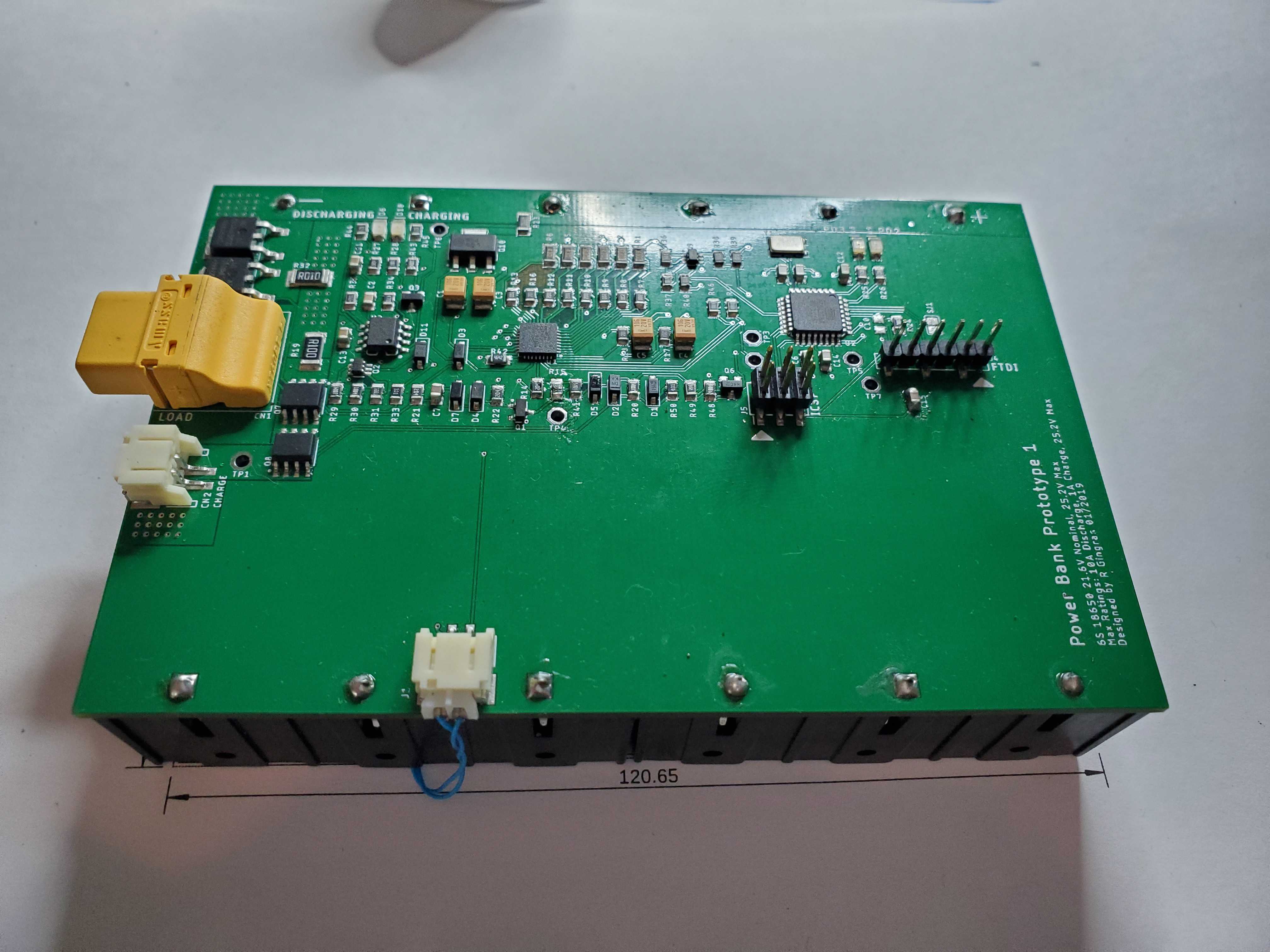
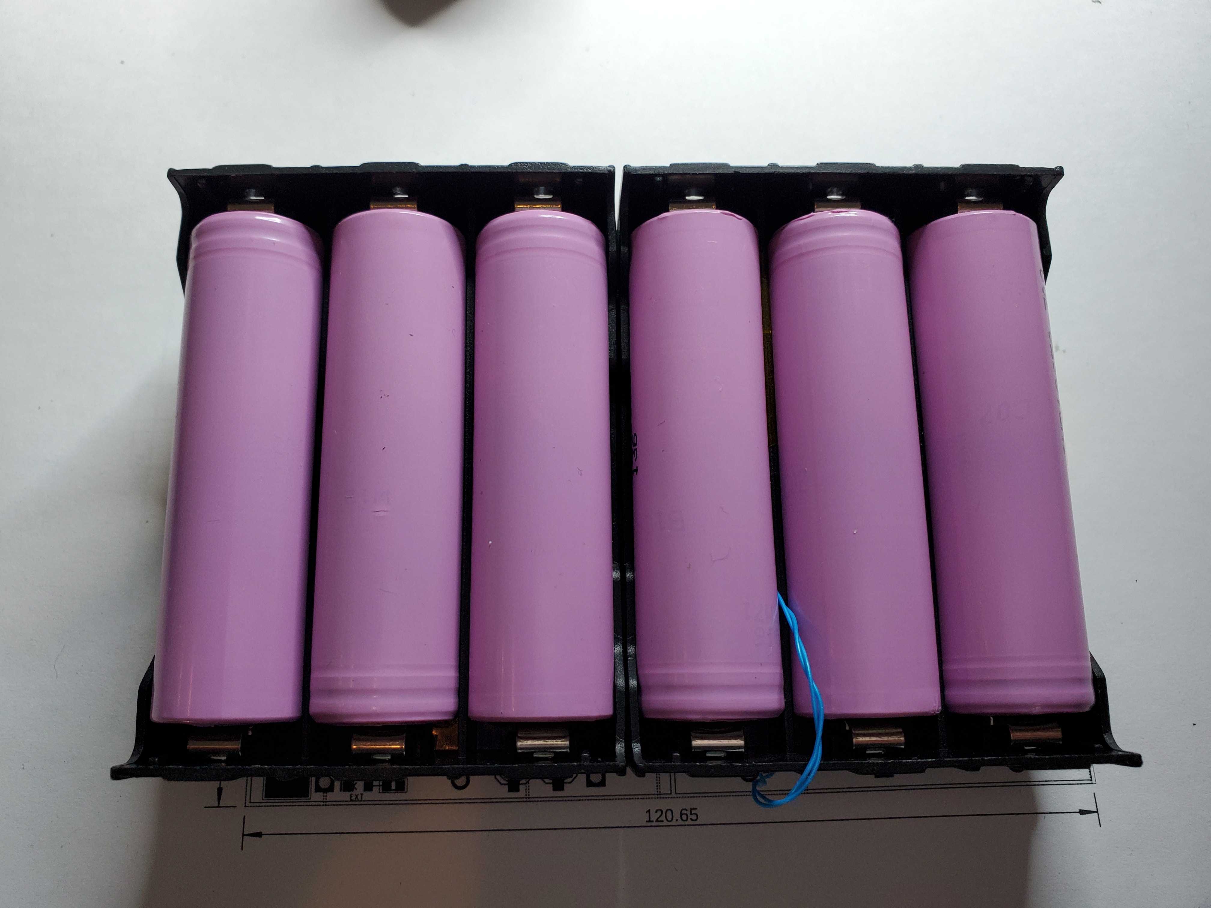
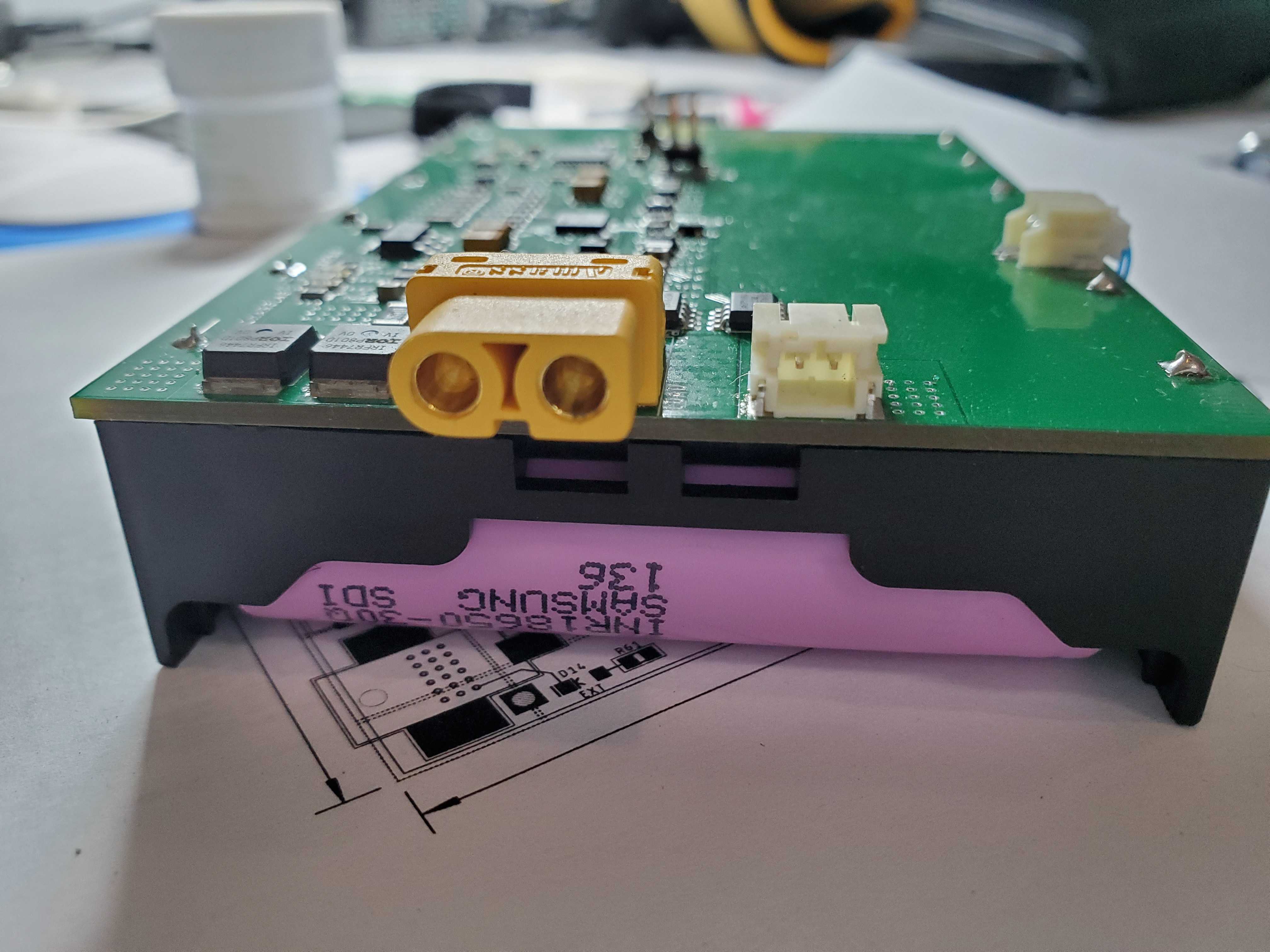
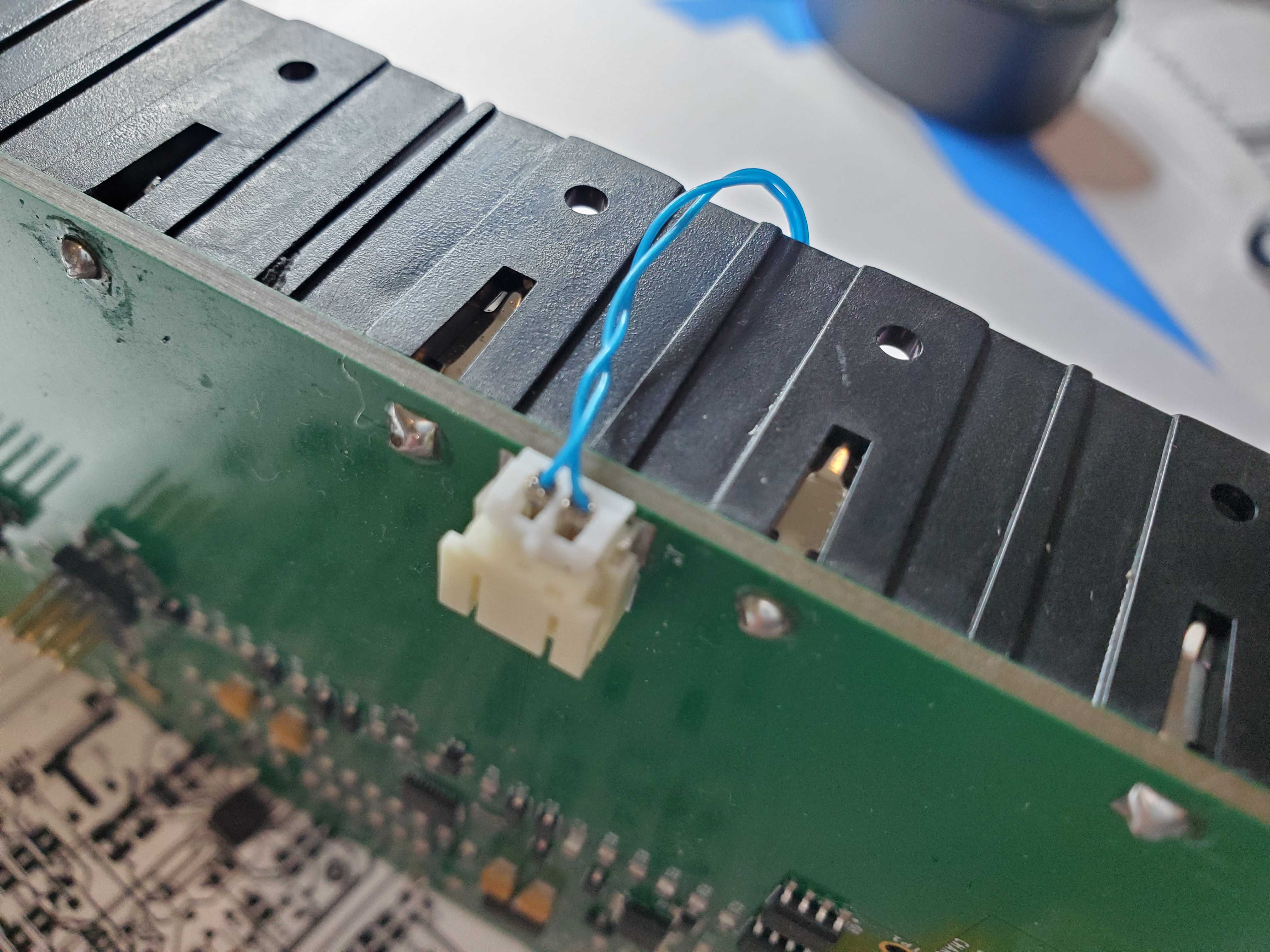
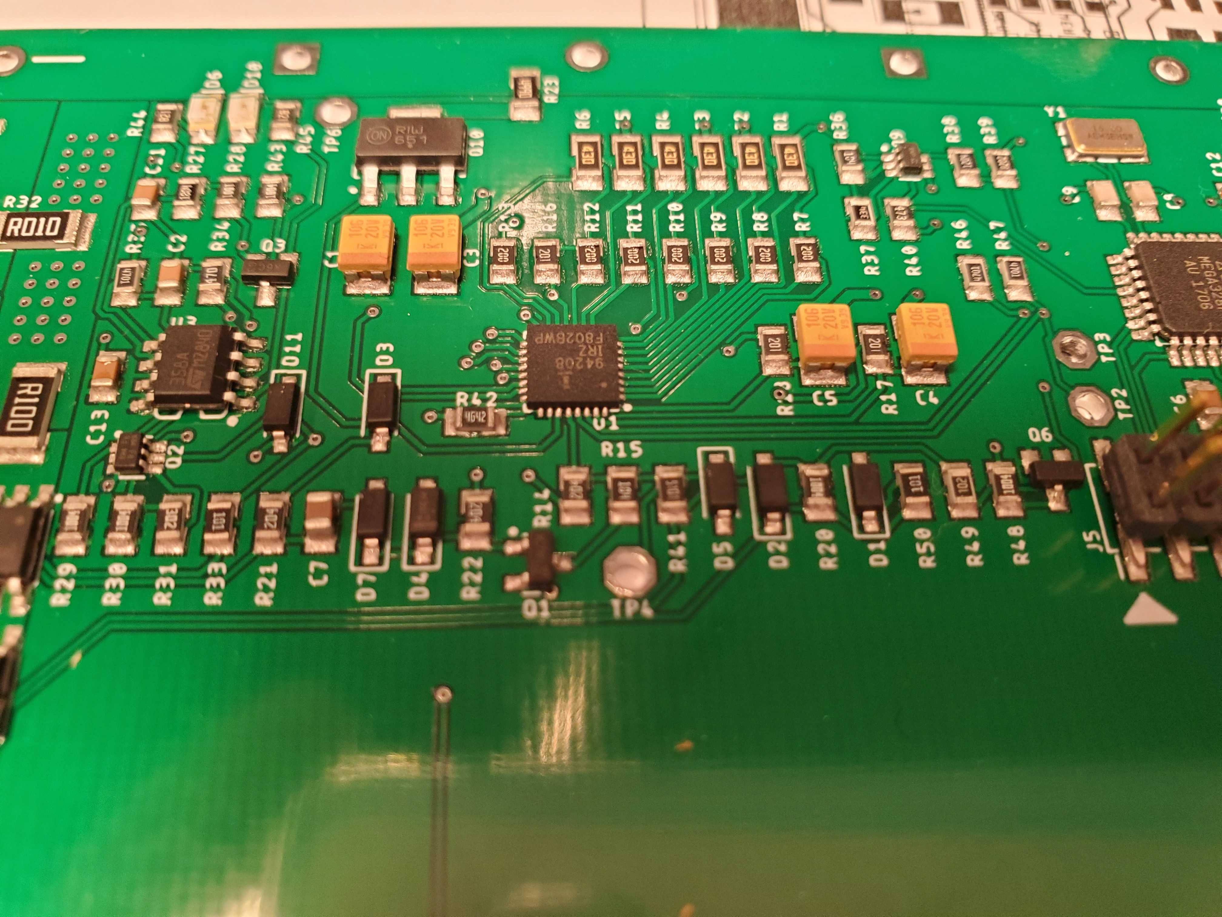
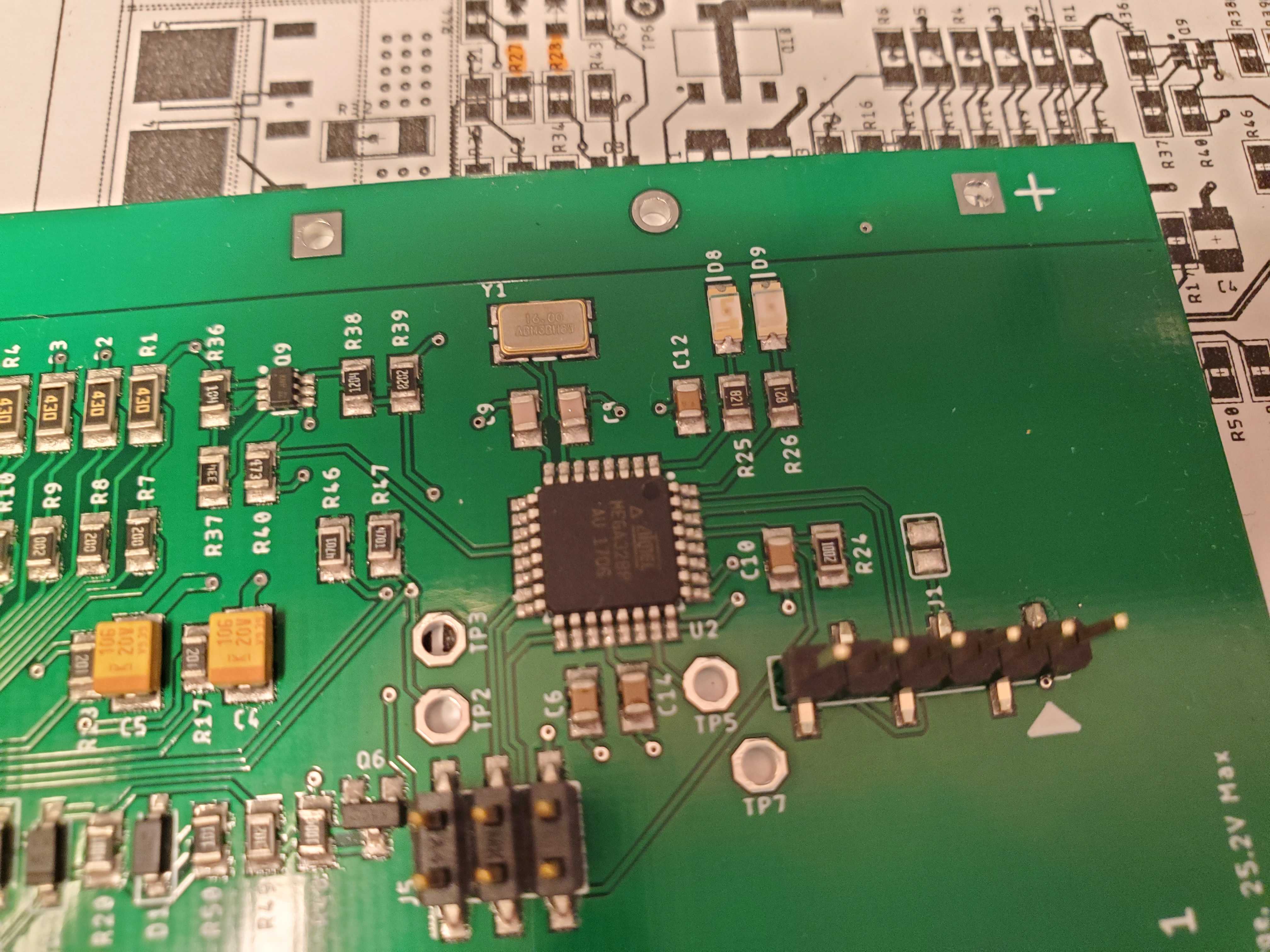
Pictures
Next Steps
My next goal is to add an integrated charging circuit to the pack. This will most likely be a current-limited boost converter that will accept about 12V input and boost it to a suitable voltage to charge the pack. I also want to include a wake-up button and LED fuel gauge for monitoring the state of charge of the pack.

Leave a Reply